Wiring Diagram Plc Dc Inputs To Ac Outputs. How to wire digital inputs. When wiring dc power the positive cable should be connected to the terminal and the negative should be connected to the terminal.
About npn sinking and pnp sourcing for inputsoutputs inputs npn and pnp. If the output does not. Any connection to dc voltage between 15 and 30 vdc is sensed as a 1.
Positive cable to negative cable to dc power supply connections must never be reversed.
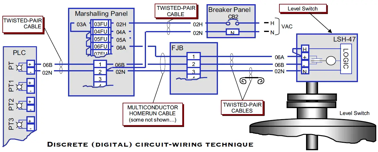
Figure 3 suppression of a a load in parallel with a plc input module b a dc load and c loads with switches in parallel and series with a plc output module click to expand diagrams go back to guidelines fusing outputs. When wiring ac supplies. In the following block diagram input and output modules are connected through the brain of plc ie. Positive cable to negative cable to dc power supply connections must never be reversed.