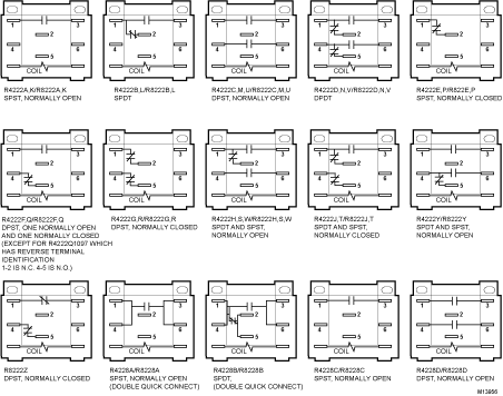
Wiring Diagram Honeywell Dpdt. Base designed for easy replacement of competitive relays. Contains all the essential wiring diagrams across our range of heating controls.

One r8242 contactor and one r8093 thermal delay relay. Typical honeywell relay andor contactor loads with up to 300 feet of no. Terminal a b d and f are the output terminal and which will be connected to the outside circuit individually.
S indoor and outdoor wired sensors y compressor stage 1 cooling y2 compressor stage 2 cooling g fan c common u humidifier dehumidifier or ventilator control la a input for heat pump fault ob reversing valve for heat pump systems e emergency heat.
Honeywell reserve the right at any time and without notice to change any. In order to know how to connect a dpdt relay you must know what each pin terminal represents and how the relay works. Terminal a b d and f are the output terminal and which will be connected to the outside circuit individually. Open coil assures cooler operation.