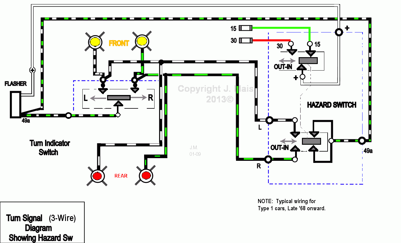
Wiring Diagram For Emergency Flashers. First 4 are obvious lf rf lr rr turn signal lights. Provides outage indication.

Then there are 2 wires blue and black. Be sure to connect the flasher as per the sketch. My scanners dead in the water.
It includes instructions and diagrams for various kinds of wiring strategies and other things like lights home windows and so on.
The flasher receives power from one of 2 fuses depending on whether or not the hazard switch is operated. The dash mounted brake warning light wires should be either gray 12 and pink or white 12 and black. Be sure to ground the signal stat. 4 way emergency flasher diagram pushpull switch continue on that same wire to a flasher unit and then to terminal 30 on the relay.