Vector Wattmeter Diagram Of Induction. The electrical machines deals with the energy transfer either from mechanical to electrical form or from. An ammeter is connected in series with the primary winding.
We measure its length on the scale diagram to nd its magnitude 46 m. Take the current i rms value as a reference vector. P active power is the actual power which is really transferred to the load such as transformer induction motors generators etc and dissipated in the circuit.
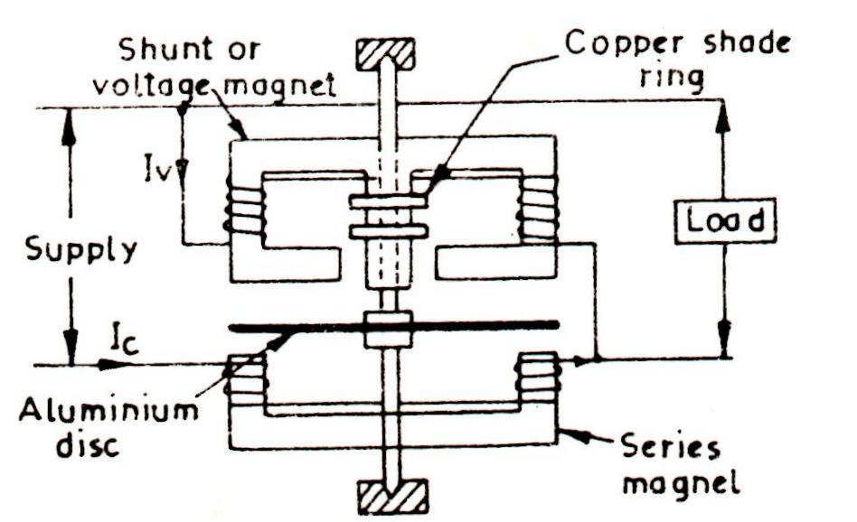
Iv the voltage coil current lags the voltage applied by an angle depending upon the coil impedance.
Representation of vector quantities symbols of units numerical values and guidance on the use of subscripts are covered in is 3722 part 1. Iv the voltage coil current lags the voltage applied by an angle depending upon the coil impedance. P active power is the actual power which is really transferred to the load such as transformer induction motors generators etc and dissipated in the circuit. The currents are 15 25 and 50 amperes while the voltage ranges selected vary between 100 and 125 to correspond with those experienced at the various revenue metering.