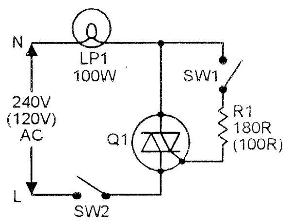
Triac Circuit Diagrams. Circuit protectors page 5 connectors terminals and wiring page 5 delay lines page 6 meters page 6 microwave and rf symbols page 7 optical and acoustical devices page 8 resistors and attenuators page 10 rotating machinery page 10 semiconductor devices page 12 shielding page 13 switches relays and vibrators page 13 temperature sensitive devices page 16. Rst reset ce chip enable dc or dc.

February 1 2016 at 1232 pm can you please send me the voltage and current full circuit and full code to display both current and voltage as shown in the post. Variety of simple motor control circuit diagrams using scr or triac. Project circuit schematic diagram is shown below.
Clipper circuits are the electronic circuits that clip off or remove a portion of an ac signal without causing any distortion to the remaining part of the waveformthese are also known as clippers clipping circuits limiters slicers etc.
The setting of p1 determines the phase of the trigger pulse that fires the triac. Switch and push button symbols. We have published complete tutorial on 555 timer which covers the theory working principle internal diagrams and almost all information related to 555 timer. Fuse and circuit breaker symbols.