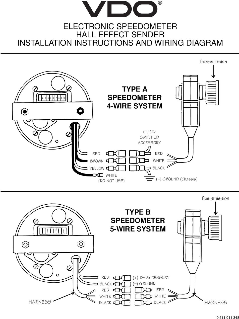
Tachometer Wiring Diagram Ac To Dc. When the vdo tachometer reading. Strip of the insulation from the black red and white covered wires.

A tachometer is an instrument that measures the rotational speed of a shaft or disk in a motor or other machine. Measure ac and dc volts on the green tachometer wire with the key on but motor not running. Refer to diagram d.
Initial setup and wiring general nstructions models ii tachometer connections iii dual voltage kbmm 2250 only voltage following d.
Disconnect negative battery cable. Combine the black and uninsulated wires which will be used for the ground into a 5 16 ring terminal. Using a master tach determine the actual engine rpm. Disconnect negative battery cable.