T Latch Circuit Diagram. Below snapshot shows it. Gated sr latch truth table.
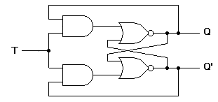
Sr q qnext qnext 0011 0110 1001 11 0 0 1 11 1 1 0 b q q s r c s r q q t 0 t 1 t 2 t 3 t 4 t 5 undefined undefined t 6 d q q s r a chapter 7 latches and flip flops page 3 of 18 a 0. When the t signal is set high 1 if the present output. I am in the middle of constructing a simple water level.
I am in the middle of constructing a simple water level.
It is a change of the jk flip flop. This is also known as toggle latch as output is toggled if t1. The circuit diagram of t flip flop can be derived from sr flip flop. It has only two logic gates.