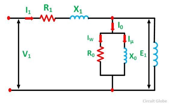
Synchronizing Machine Diagram Of Induction. Pull out protection must be provided otherwise the motor will run as an induction motor drawing high current with the possibility of severe motor damage. Volt per herz speed control of an induction motor.

A larger than for leading pf internal generated voltage e a is needed to form the same phase voltage. It is totally self synchronizing with the grid it is feeding power into. It stays in sync and delivers energy as long as it is driven at an rpm higher than its synchronous speed.
Any synchronous machine either motor or a generator can provide active power to or get active power from a system connected and provide reactive power to and get reactive power from the system.
26 power flow diagram of an induction motor 27 factors determining the torque 28 torque slip curve stable and unstable zones. The invention is a system and method for synchronizing an induction machine to an electrical grid. Elementary 3 phase round rotor synchronous generator. 1 synchronous machines 24 40 2 induction motors 16 25.