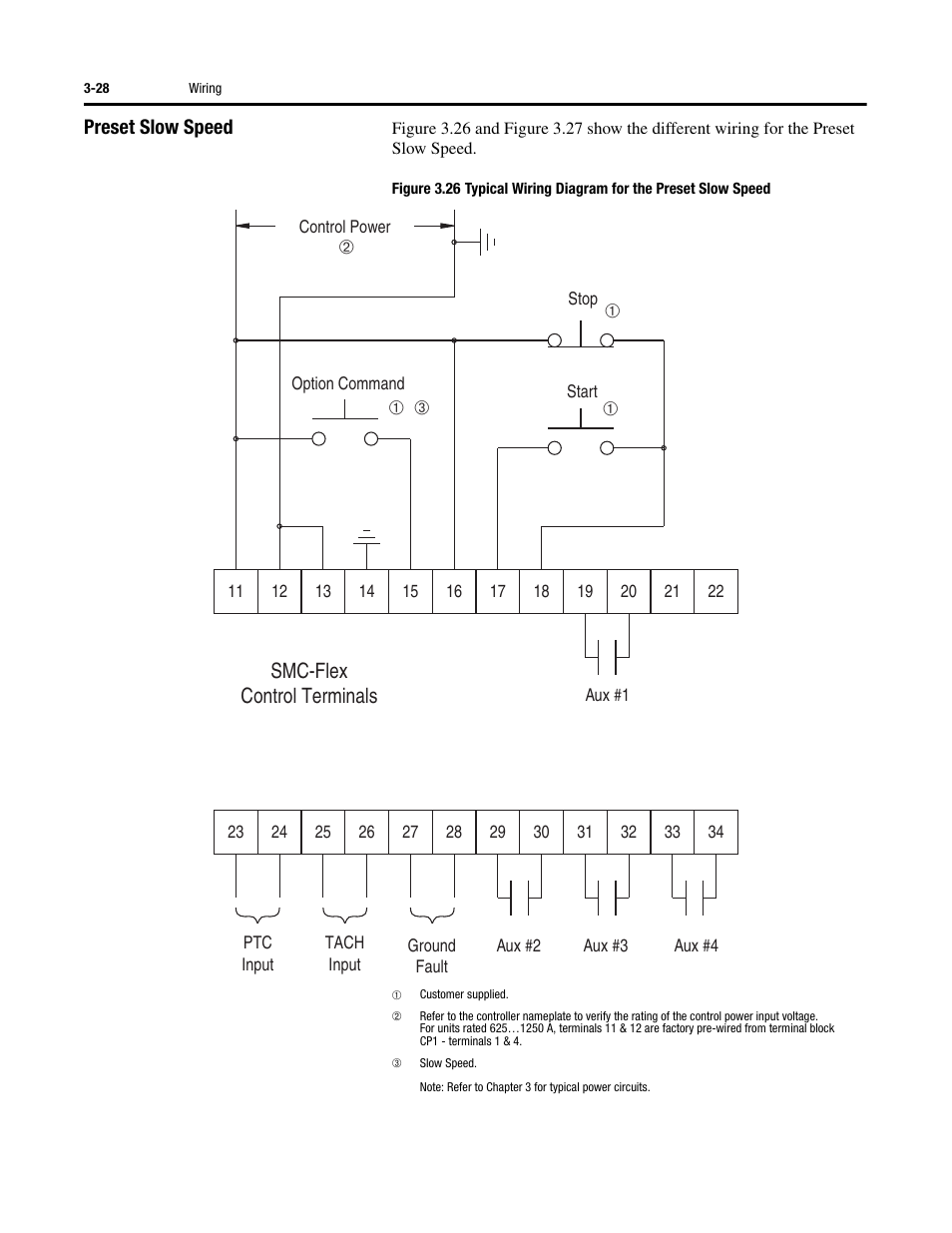
Smc Flex Wiring Diagram. Lable for block disk the labels shown below are used on manifold stations containing. Typical wiring diagram figure 5.

Allen bradley 709 3 phase starter wire smc soft low voltage starters delta and manualzz flex quick start bulletin pdf free wye solid state 150 e147nce fc size 1 with selection guide practical machinist largest combination motor 512 bab 24 140m c2e b16 series c doent 10281863 specifications plc program for guardmaster safety relay 22. How to create a pneumatic circuit sketch using smc draw great free software available online 32 push button control of single acting cylinder. Smc flex getting started 5 figure 4.
Smc flex smart motor controller 33 specifications specifications wiring diagram line controller 9customer supplied.
This component is a solid state controller that has input line voltage requirement of 200 460vac 3 phase 5060 hertz control voltage of 100 to 240v ac 5 to 480 a units with rated current output of 85 amperes rated power of 60 horsepower at 460vac. Smc flex smart motor controller 33 specifications specifications wiring diagram line controller 9customer supplied. Product selection is the sole responsibility of the user regardless of any recommendations or suggestions made by the factory or its distributors. Allen bradley 709 3 phase starter wire smc soft low voltage starters delta and manualzz flex quick start bulletin pdf free wye solid state 150 e147nce fc size 1 with selection guide practical machinist largest combination motor 512 bab 24 140m c2e b16 series c doent 10281863 specifications plc program for guardmaster safety relay 22.