Sample Pneumatic Diagram. Many devices that people use in everyday life are based on pneumatics. Note you can also insert the vertical or horizontal pipes first and then insert the components onto the pipe.
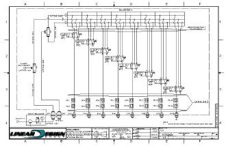
Outline of pneumatic circuit diagram creation program symbols corresponding to the product part number can be selected. Mechanical engineering solution 8 libraries are available with 602 commonly used mechanical drawing symbols in mechanical engineering solution including libraries called bearings with 59 elements of roller and ball bearings shafts gears hooks springs spindles and keys. Pneumatic circuit diagrams in practice usually consist of several circuits that means you have a lots of valves and associated actuators cylinders motor.
Its very good for real time measurement the use of this software is very professional.
The examples of pneumatics were based on antiquity which should come as no surprise since what we understand today by industrial pneumatics has developed in europe only since the 1960s. To read these schematics correctly according to their signal flow proceed as shown in the animation below. 6 basic pneumatic system components regulator regulators control circuit pressure or force. This is true with devices used by consumers as well as in industrial applications.