Reverse Return Piping Diagram Geothermal. Is the least efficient diagram among the electrical wiring diagram. A reverse return system is a type of closed loop system where the return header is connected to the most hydraulically remote load as shown in image 1.
Here is a diagram of a typical closed loop well geothermal system utilizing a reverse return piping layout. Geothermal systems tend to be designed with higher flow rates that result in higher pump work than. Expansion tank must be rated for use with potable water.
A reverse return system is a type of closed loop system where the return header is connected to the most hydraulically remote load as shown in image 1.
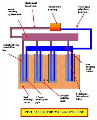
This larger diameter means more surface area of contact and better heat transfer. The use of reverse return piping common headers and carefully sized piping can all help to reduce the pressure drop. This can prevent a lot of damage that even derail electrical plans. On a standard residential vertical installation each ton of heat exchange is a 150ft 6 inch drilled hole and a 510ft x ¾ u bend hdpe polyurethane plastic pipe is installed and grouted to mo dnr standards each ton needs to be spaced out 10 to 12ft once all the holes are drilled they will be piped into a reverse return 1 ¼ header pipe that is piped to the geothermal unit.