Pwm Circuit Diagram. The block diagram required for the generation of a simple pwm is shown in the following. A pwm inverter is a type of circuit that uses modified square waves to simulate the effects of alternating current ac which is suitable for powering most of your household appliances.
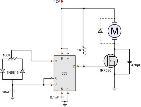
A pwm inverter is a type of circuit that uses modified square waves to simulate the effects of alternating current ac which is suitable for powering most of your household appliances. 0 290 less than a minute. Circuit diagram the following image shows the circuit diagram of 555 timer pwm generation.
17102020 explore soltans board pwm on pinterest.
This circuit uses the common 555 timer to create. Only the width changes. When it comes to the generation of high voltages. C2 charges through diode d1 and discharges through diode d2.