Push Barge Diagram. Normally a lasing line or rope from the forward head of one barge to the after head of a barge along side. By 1880 distinct types of steamboats were developed including towboats.
Most tug and barge safety regulations focus on hardware and yet experience shows that a good safety record depends upon the safety culture of the entire company. A a view from above of two tugboats pushing on a barge. The main current will help the stern in staying close to the bank.
A range of drilling or piling rigs may be mounted on the barge to carry out survey sampling piling for flood defences or eg.
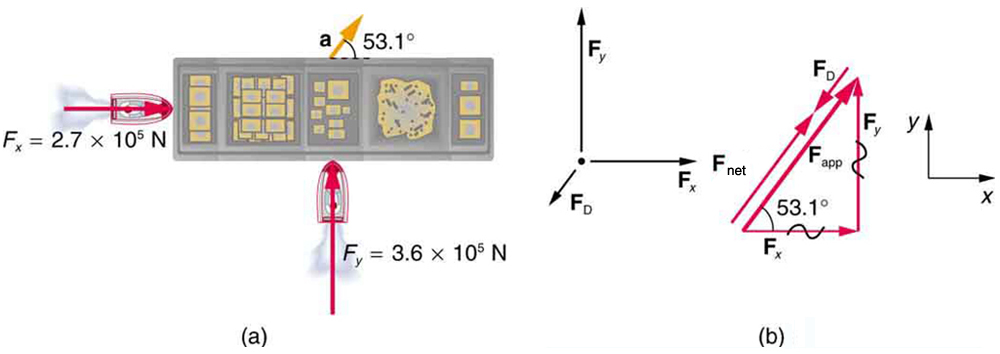
Figure 64 a a view from above of two tugboats pushing on a barge. The main current will help the stern in staying close to the bank. The elements that are highlighted in orange are selected for the forming limit diagram presentation. The first tugboat exerts a force of 27 10 5 n in the x direction and the second tugboat exerts a force of 36 10 5 in the y direction.