Profinet Wiring Diagram. Prof inet connectors 67 outside rj 45 variante 14 pas 61076 3 117 sc rj variante 14 pas 61076 3 117 prof inet 24 power supply connector 67 outside prof inet 400 volt power bus connector. Profinet interface 178 mm 226 mm 226 mm 226 mm depth of the inverter with ussmb canopen or profibus interface 155 mm 203 mm 203 mm 203 mm additional depth when the operator panel is attached 21 mm with iop intelligent operator panel plugged in 11 mm with bop 2 basic operator panel plugged in.
The components available for your profinet infrastructure depend on the harshness of the. This is where you will connect the green and the red wire. Most modern communications equipment can auto sense which type you are using but some still need the correct cable pinout.
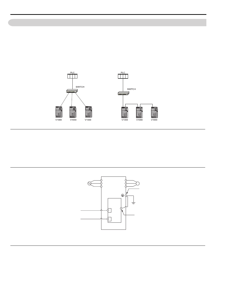
Standard profinet cable as any 100 mbps ethernet cable is described as a 2x2 cable with 4 wires.
See the column with the relevant cable separation type for the appropriate distance for each cable type. Page 60 the complete circuit diagram is comprised of the following components. Simple integration with existing ethernet systems. Warning there is a risk of contact to live power cables.