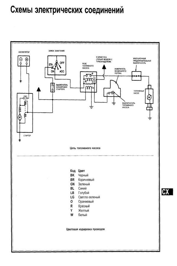
Probe Wiring Diagrams. It is very important that each of the three wires used in the measuring circuit are equal in terms of both conductor size and length. 3 connection designation relay control module on relay panel shows the individual terminals in a multi point connector.

399 sensor with internal preamp wired to rosemount 1000 series 399 sensor with internal preamp wired to rosemount transmitter. Trace the wiring till you can see where a short may have taken place. D0b1e caterpillar 3406e wiring diagram digital resources.
For the studs you can use brass paper fasteners like this or small nuts and bolts nails or screws.
First find the problem area on the wiring diagram. Or in an 84 to 89 240 you may use the ac power on wire. When wiring is complete it is recommended that the ceiling mounting plate is fitted to the sensor body and fixed to the ceiling as follows see diagram i for ceiling mounting assembly method. A12 central relay and fuse box b11 coolant temperature sensor b17 9 charge air temperature sensor b19 catalyst temperature sensor b19 12 temperature sensor in front of the particulate filter b19 12x1 electrical plug connection of the temperature sensor in front of the particulate filter.