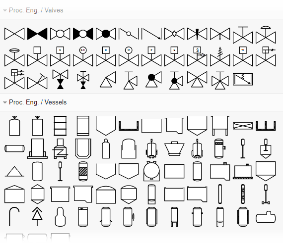
Piping Instrumentation Diagram Tutorial. V pid process designer 2016 45 2 in the article selection dialog box select a pipe class from the list and click ok. Symbols used in the pid the first thing to do with any pid is to try to identify the various instrument symbols used.

On the developed pid fv 100 is the control valve provided to regulate flow. Explain a basic measurement system. Learn the piping and instrumentation diagram pid used in industries.
Che 4253 design i piping instrument diagrams piping and instrumentation diagram for benzene distillation adapted from kauffman d flow sheets and diagrams.
This can usually be gotten from the library of symbols located somewhere in the pid legend. This is a basic pid tutorial for beginnersget plc tutorials herehttpsinstrument. A piping and instrumentation diagram or pid shows the piping and related components of a physical process flow. Instrumentation type location identified path between instruments control devices indicated piping size and type identified for all lines.