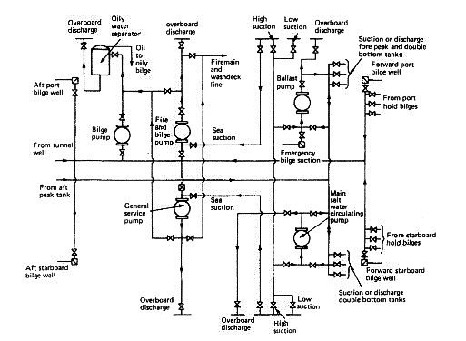
Piping Diagram Ballast System. Navigation and signalling lights power supply and monitoring system. Description title drawing no.

Tanker ship ballast piping diagram marine piping systems slideshare april 18th 2019 ballast system for safe operation at least two ballast pumps are to be connected to ballast tanks stripping eductor can also be used for emptying the bilges in cargo holds with 2 non return valves between hold and system ship side valve material. In the case of passenger ships each compartment or section of a compartment may be. All cargo ships are provided with pumping and piping arrangements so that any watertight compartment or watertight section of a compartment can be pumped out when the vessel has a list of up to 5 and is on an even keel.
Ballast reg 1 18 3 1 the segregated ballast system should be a system which is completely separated from the cargo oil and fuel systems as required by regulation 1 18.
Fi overflow system s010 piping diagram pd ap internal drain system s010 piping diagram pd ap. Therefore ballast water systems are used for the purpose of providing weight at strategic locations within a vessel. Piping diagram bwms integrated with existing bws bwms operation manual ballast water management plan d1d1d2d2 type approval certificate tac statement of acceptance of the bwts if applicable hazard analysis if applicable commissioning procedure electrical description of changes updated electrical power single line diagram. Fi overflow system s010 piping diagram pd ap internal drain system s010 piping diagram pd ap.