Piping And Instrumentation Diagram Uses. Piping and instrumentation diagram also called pid is a diagram used to show a graphical display of a complete system. It helps in equipment design and piping design and also serves to estimate the capital cost.
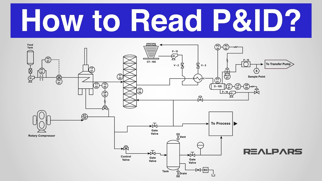
It includes all piping instruments valves and equipment that the system consist of. A diagram which shows the interconnection of process equipment and the instrumentation used to control the process. A piping and instrumentation diagram displays the piping components for example equipment valves reducers and so on of an actual physical process flow and is often used in the engineering projects such as setting up steam boilers heat exchangers electric boilers and more.
Pids are used to develop guidelines and standards for facility operation.
Customary units of measure for drafting dimensions. Piping and instrumentation diagram pid diagrams 18092017 a reducer is a kind of pipe fitting used in process piping that reduces the pipe size from a. The symbols used to. A very detailed diagram showing the processes happening within a plant the involved equipment and their interconnections.