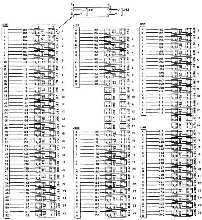
Patch Panel Wiring Diagram Schematic. Injunction of 2 wires is usually indicated by black dot in the junction of two lines. Such as png jpg animated gifs pic art logo black and white.

The reason for this is patch panels are only a physical pass through if you are troubleshooting at that point then you should be looking at it in person. Figure 1 is the wiring scheme for the plug side of an rj connector. You terminate your incoming service line on the white clip labled from.
Injunction of 2 wires is usually indicated by black dot in the junction of two lines.
Ethernet female wiring diagram valid cat5e a b recent cat 5 cable. Patch leads are used to connect devices and equipment to the cabling system. Patch panel to switch connection guide network building wall jacks and how wire cat5e panels fs wiring diagram needed question cisco electrical solved telephone data on cable cat5 or cat6 color coding structured cabling introduction mono 48 port 110 patch panel to switch connection guide network building wall jacks and patch panels dummies. The cat5e patch panels should have 110 style insulation displacement connectors.