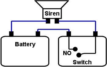
Part Alarm Diagram. Diagram 52a volume 1 diagram 82a volume 2 with the associated text in paragraph 514 volume 1 and 828 volume 2 will be updated to remove with a thermoplastic core. Installing a smoke detector circuit for a hardwired home security system.

Ansiieee standard device numbers 1 master element 2 time delay starting or closing relay 3 checking or interlocking relay 4 master contactor 5 stopping device 6 starting circuit breaker 7 rate of change relay 8 control power disconnecting. So um3561 activated and start producing sound with speaker. Circuit diagram for basic alarm with delayed trigger.
This simple yet effective lextek alarm will help to protect your bike.
Alarm system wiring from the transformer location to the main panel should be 4 conductor fire wire 22 gauge minimum. See the alarm wiring guide for more information. Circuit diagram for basic alarm with delayed trigger. Part 2 high and low voltage cutoff circuit diagram high and low voltage delay and alarm for home hey guysin this video i am going to show you how to mak.