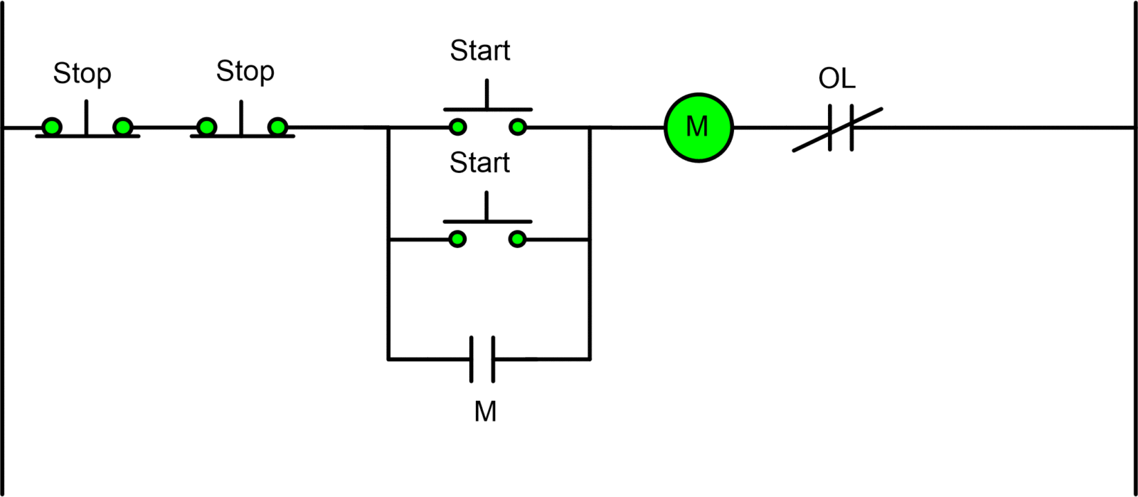
One Line Diagram 3 Wire Start Stop Station. One of the common control wiring circuits used is known as two wire or low voltage release lvr. Here is a simple diagram if you want to make this a control signal just add the starter and wire to the coil instead of the motor.

Would like to have detailed instructionsdrawings of proper wiring of startstop stations for multiple motors of single phase and three phase ac 120v 240v 480v for applications such as conveyors. The wire between terminals 95 and 13 must be removed and the stop buttons must be wired in the. 1 j start 2 3 stop i no.
B1 mcb 5a 3 phase m1 motor 15kw 380v 3phase 1 magnetic contactor 220vac tor thermal overload relay 28a s1 push button switch ptb non latching stop switch s2 push button switch ptm non latching start switch l3 pilot lamp 220vac.
Start stop 3 wire control. Then do the connection between cb and mc. I operation depressing the start button energizes coil m hold in contacts m and maintains the circuit after the start button is released. For 3 phase motor controlling diagram and procedure follow the below tips.