Omega Rtd 3 Wire Diagram. Omegas new omtbv7 w terminals aredesigned to meet the three most importantcriteria when selecting a terminal block line ease of wiring secure connections anddurability. Locate the model number in table 3 1 or 3 2 and set the resistance source to the lo in value.
When the transmitter is mounted inside a protection head such as the omega nb1 protection head two copper wires now carry the temperature signal and dc voltage to operate the. Terminal identification cn730 cn710 cn740 14vdc or 4 20ma or 0 10v out1 no com 1 6 2 7 rtd 3 11 12 l ac 100 24ov 5060hz 5va n 13 in tc 49 5 10 data rs 485 data alm2 14 alm1 15 com 3a 250vac 3a 250vac 8. Figure 4 rtd wiring diagram.
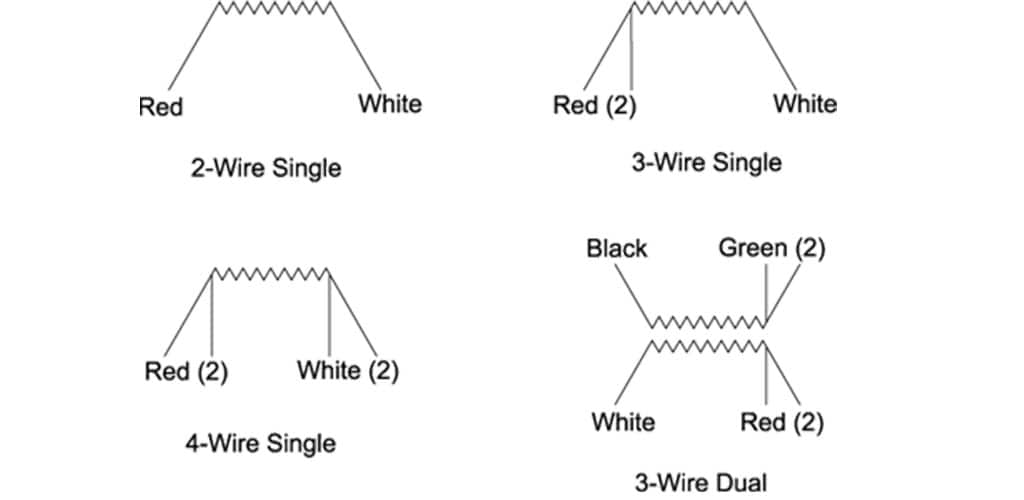
If three identical type wires are used and their lengths are equal then r1 r2 r3.
Precision pt100 class a sensing element. Precision pt100 class a sensing element. Input wiring for thermocouple current and rtd. M8 socket connector one end stripped leads on the other.