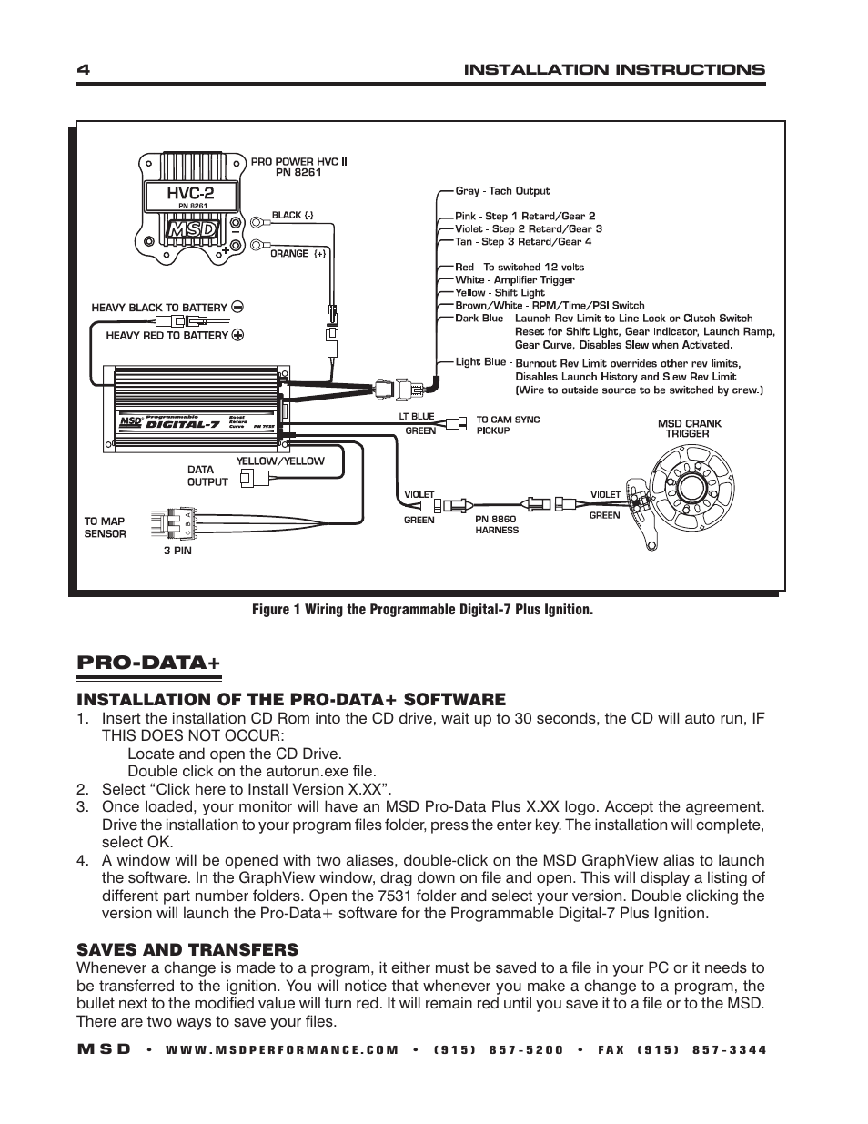
Msd 7531 Wiring Diagram. Connect the gray tach wire of the 7531 to the m terminal on the 8. Msd pro mag timing control com tach converter 8973 to 7531 reva holley motor life ignition information alkydigger technical info wiring diagrams and tech notes manualzz in pdf format 12 mb 8106 electronic points box 20 amp generator pn 8132 mounting 8610 chevy small block crank trigger kit user manual page 7 8 also for 8636 chrysler big 8615 balancer wheel 44.

Starting at 101 a. Msd 7531 wiring diagram msd 7531 digital 7 plus ignition ok ive been asked to help out a good friend with his 7531 msd box. 1 ignition control pn 7531 1 msd pro data cd rom 4 vibration mounts screws 1 shielded cam sync harness 1 9 pin computer harness accessories hand held monitor pn 7550 inductive cam sync pickup kit pn 7555 non magnetic cam sync pickup kit pn 2346 manual launch rpm control pn 7551 digital shift light pn 7542 map sensor see page 9.
Connect the white points wire of the bs3 to the white points wire on the 7531.
Solid core spark plug wires cannot be used with an msd ignition control. Solid core spark plug wires cannot be used with an msd ignition control. When 12 volts are applied to this wire it will activate the launch rev limit. Msd programmable digital 7 plus.