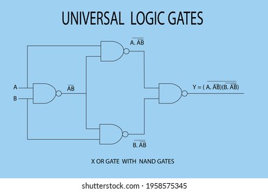
Logic Gates Diagram Images. The interconnection of gates to perform a. 1schematic diagram in a logic symbol 2truth table 3boolean expression 4timing diagram 5expressionin programming language eg.

Initially when both the inputs are at zero making the transistors offopen circuit. And gates are represented diagrammatically as. Thus the vcc does have a path to the output hence the final output is zero.
The schematic diagram boolean equation 2 to 1 multiplexer using logic gates in what is a operation types digital electronics experiment four possible circuits for mux and multiplexing design steemit introduction ppt figure 6.
A not or operation is known as nor operation. An or gate is a logic circuit that performs an or operation on the circuits input. No image atribute value. A simple two input logic nor gate can be assembled using a resistor transistor connected together as explained below with the inputs connected directly to the transistor bases.