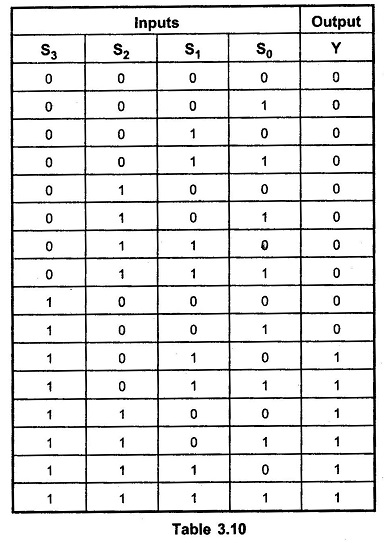
Logic Diagram Of Bcd Adder. Mary livinsa etce and mrs. Addend augend 4 bit binary adder carry out co carry in output carry 0 z 0 z 3 z 2 z 1 s3 s2 s1 s0 4 bit binary adder addition result in binary detection circuit correction factor 0 6 the two bcd digits together with the input carry are first added in the top 4 bit binary adder to produce the binary sum.

The two bcd digits together with the input carry are first added in the top 4 bit binary adder to produce the binary sum. The four bit parallel adder is a very common logic circuit. Bcd to 7 segment logic diagram pspice 7 segment display digital integrated circuits march 7th 2018 its operating principle is to input a four bit bcd binary coded decimal value and energize the proper output lines to form the corresponding decimal digit on the 7 segment led display the bcd inputs are designated a b c and d in order from least.
Start date oct 16 2011.
The latter six combinations are invalid and do not occur. The two decimal digits together with the input carry are first added in the top 4 bit binary adder to. Here to get the output in bcd form we will use bcd adder. Addend augend 4 bit binary adder carry out co carry in output carry 0 z 0 z 3 z 2 z 1 s3 s2 s1 s0 4 bit binary adder addition result in binary detection circuit correction factor 0 6 the two bcd digits together with the input carry are first added in the top 4 bit binary adder to produce the binary sum.