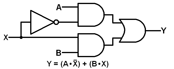
Logic Diagram Of 2 To 1 Multiplexer. Q ai0i1 ai0i1 ai0i1 ai0i1. As we only have one control line a then we can only switch 2 1 inputs and in this simple example the 2 input multiplexer connects one of two 1 bit sources to a common output producing a 2 to 1 line multiplexer.

One of these 4 inputs will be connected to the output based on the combination. Ppt figure 6 1 a 2 to multiplexer powerpoint presentation free id 3296517. If you look at the logic diagrams they all show the selector pin as not inverted.
A 2 to 1 mux logic symbol switching analogy as shown d 0 is an applied input to one of the and gate and d 1 is an applied input to the other and gate.
Which implies that the second 21 mux table is the correct one. The block diagram and the truth table of the 2 1 multiplexer are given below. Firstly i will introduce what is mux. For example the diagram and truth table in this tutorial.