L2 V Wiring Diagram. I have also seen different designations in various countries ive worked in so ultimately. My electrical wiring project involves wiring a 240volt motor.
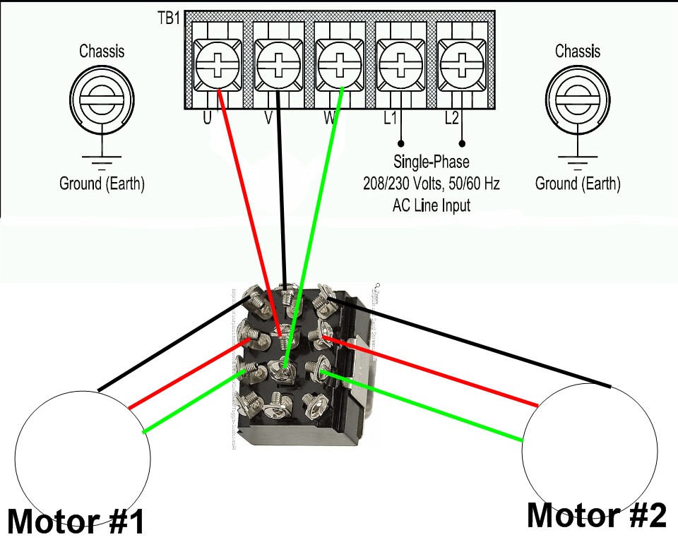
Diagram dd6 diagram dd7 m 1 ln e diagram dd8 ln e l1 l2 l3 s c z1 u2 z2 u1 cap. Single phase motor wiring diagrams single voltage motor 208 230v ccw cw l2 l1 t1 t8 t4 t5 t1 t5 t4 t8 dual voltage motor 115v or 208 230v 208 230v or 460v low voltage high voltage ccw cw ccw cw l2 t1 t3 t8 t2 t4 t5 t1 t3 t5 t2 t4 t8 l1 t1 t3 t8 t2 t4 t5 t1 t3 t5 t2 t4 t8 l1 l2 dual voltage motor with manual overload mo 115v or 208 230v 208. Wiring devices nema wiring diagrams 1 15r l1 15r ml1 r 125v w sys.
L1 l2 l3 mean the line coming in.
They can be accommodating when determining a fault in the connections installing new wires and devices locating electrical. V 1 phase 60 hertz. Wiring devices nema wiring diagrams 1 15r l1 15r ml1 r 125v w sys. Each component ought to be placed and connected with other parts in particular way.