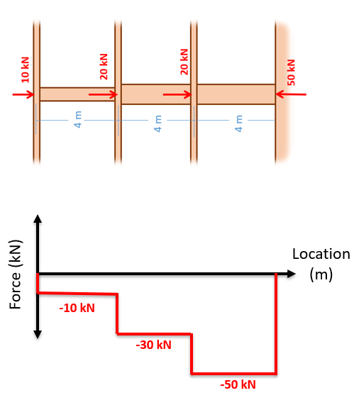
Internal Torque Diagram. Generally it is advantageous to represent the distribution of internal forces moments and torques by internal force diagrams. Find resultant torque about axis a a for the.

Bobcat 7753 skid steer loader service manual pdf. The torque diagram will plot out the internal torsional moment within a shaft that is supporting multiple inputs andor outputs along its length. We have section propertythe polar moment of inertia for the shaft is j 75 mm4 497 107 mm4 shear stresssince point a is at c 75 mm b 189 nmm2 189 mpa ans.
Find resultant torque about axis a a for the.
Extend lines of action for each force. Mechanics of materials instructor solutions manual exp 4667 the solid 30 mm diameter shaft is used to transmit the torques applied to the gears. Determine the shear stress at points a and b and sketch the shear stress on the volume elements located at these points. The torque diagram of a shaft is analogues to the shear force and bending moment diagram of a beam.