Instrument Logic Diagram. Logic with title box 38 figure 26. Instrument logic diagram for actuated valve esdpsd fg pump fan motor mcs tcs.
For example if the result of the logic operation is to completely open a valve it should be so stated and not be stated as being not closed 2. Master alarm trip schedule. Function and purpose of pids pids are foundational to the maintenance and modification of the process that it graphically represents.
A piping and instrumentation diagram or pid shows the piping and related components of a physical process flow.
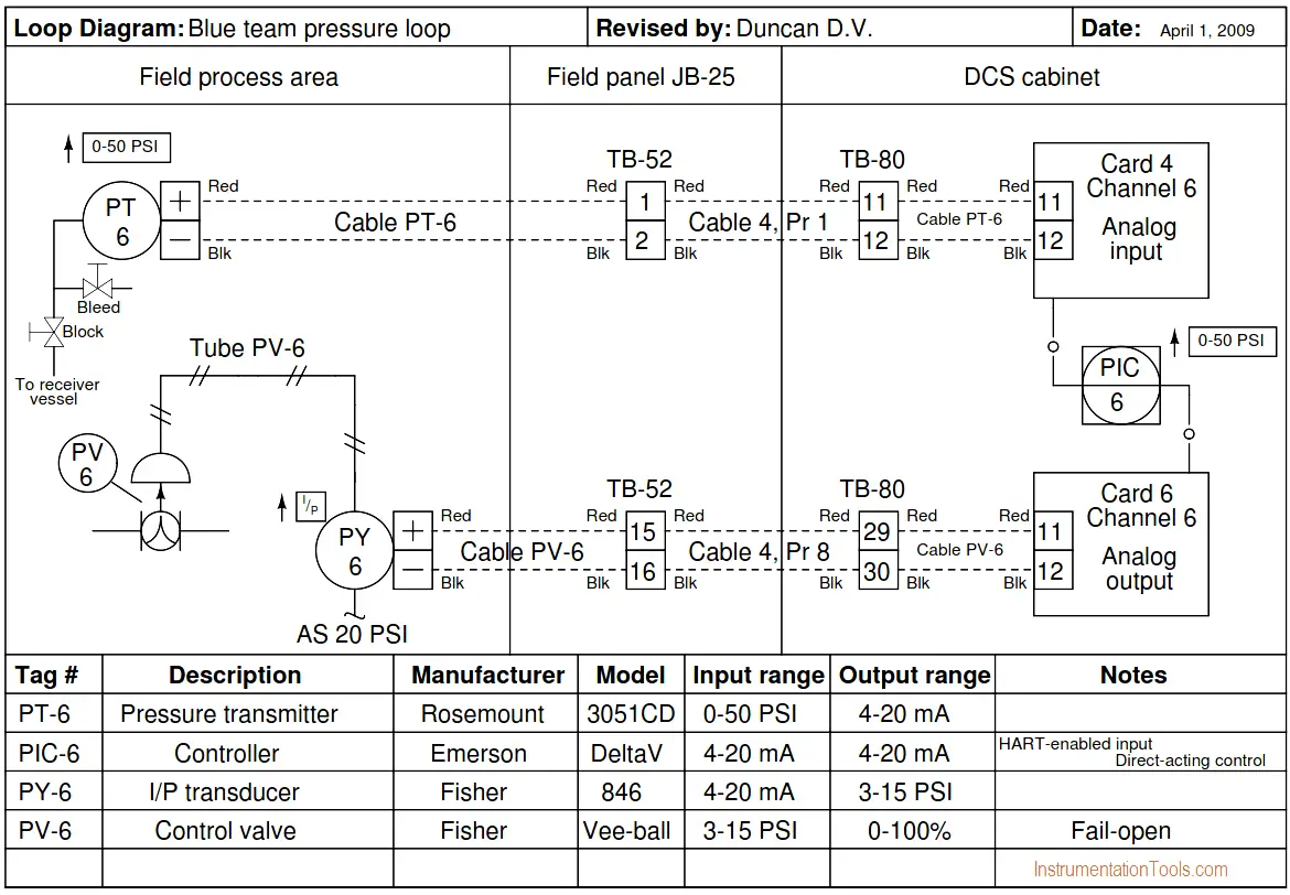
The most commonly prepared drawings for instrumentation and controls are logic diagrams instrumentation index loop diagrams and interlock diagrams or electrical schematics. The block diagram shown above is of basic instrumentation system. Detail of wiring diagram with connection tables 42 figure 30. Serial link data listings and addresses.