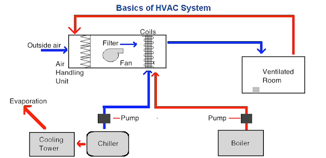
Hvac Cycle Diagram Pdf. The points which are required for engineering calculation are from h 1 to h 6 as shown in the figure 1 6. The cooling coils are fed from a source of cooling such as chillers a cooling tower or dx unit.
At point 1 the refrigerant leaves. The p h diagram is another convenient diagram often used to illustrate the refrigeration cycle. 1 2 polytropic compression on the condensation pressure for comparison 1 2 isentropic compression 2 2 isobaric cooling deheating of the superheated steam in addition there are also pressure losses in the.
76 ice bank control 84 761 control of the glycol water mixtures temperature 84 762 control of the diverting valve according to operating mode85 763 ice bank charging control 85 77 economic considerations 85 81 introduction 86 82 field of application of the absorption.
Motor vehicle air conditioning mvac system operation and the refrigerant cycle. The metering device component 3 on this air conditioning circuit and cycle diagram is the dividing point between the high. T s diagram for actual vapor compression cycle. So refrigeration cycle should be known to understand the refrigeration system.