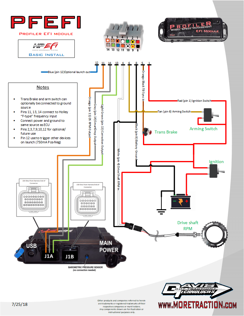
Holley Hp Wiring Diagram. This harness connects to the 8 pin metripak inputoutput connector located in most holley efi main harnesses terminator harness have a 3 pin io connector. Crank position sensor crank holley efi systems work with 24x and 58x ls crank sensors.

I have searched and searched for a wiring diagram for this combination with no luck. If this is your first visit be sure to check out the faq by clicking the link above. Bbk 80mm tb holley dominator mpfi dis 36 1 crank trigger 1x cam sync 200a 3g alternator optima red battery r134a ac.
Trying to sort through all the iac wiring info and other random questions.
Wire color type can be configured as ecu pin connector pin whiteblue. Holley hp efi systems are equipped with 4 programmable inputs and 4 programmable outputs that are ideal for most vehicles with a single power adder. This manual contains information and diagrams related to wiring most holley efi products including ecus ignition systems nitrous systems watermethanol injection systems sensors and more. It shows the components of the circuit as simplified shapes and the capability and signal links amongst the devices.