H Bridge Circuit Diagram. The h bridge configuration is a common way to change the direction of the power supply. Operating supply voltage up to 46 v.
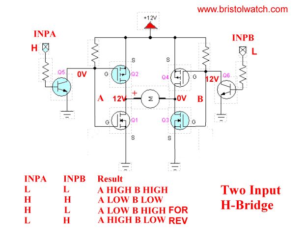
Figure 1 shows the schematic diagram of the h bridge dc motor driver. 26 the right mosfets q2 and q4 in the simplified diagram above select the motor rotation direction. A dc motor is connected between the two commons.
L298n schematic diagram.
26 the right mosfets q2 and q4 in the simplified diagram above select the motor rotation direction. A circuit analysis. N1 n2 n3 n4 not gates from the ic 4049 are arranged as a voltage doubler circuit which generates about 20 volts from the available 12v supply. The frequency is set by r1 r2 and c2.