Function Block Diagram For Ils. The diagrams are colorcoded and can be zoomed in to view the whole diagram or specific areas in more detail. Set all inputs except one equal to zero.
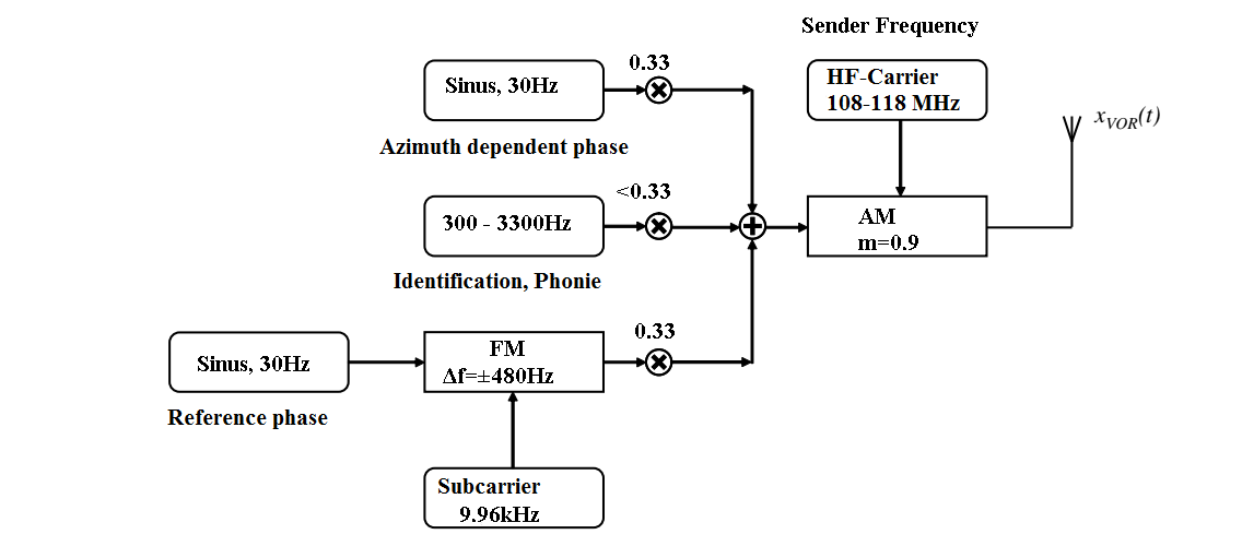
Step 3 get the overall transfer function by adding all those transfer functions. Block diagrams consist of blocks these represent subsystems typically modeled by and labeled with a transfer function signals inputs and outputs of blocks signal direction indicated by arrows could be voltage velocity force etc. Ils block diagram the localizer signal the modulation type of all ils transmitters is the good old amplitude modulation am.
The diagrams are colorcoded and can be zoomed in to view the whole diagram or specific areas in more detail.
Figure 10 3 block diagram of a closed loop system with a feedback element. Standard function blocks what this chapter contains this chapter describes the standard function blocks. H s feedback transfer function 3. A functional block diagram abbreviated as fbd is a graphical representation of a functional process via blocks and diagrams that is easier for a reader to understand and interpret.