Eye Diagram Signal Clock. You will see in just a few seconds that the eye diagram has begun to form. Eye diagram tp1 connection for source compliance tests apply the worst.
The resulting eye diagram will deviate to a greater or lesser degree from the rectangular box that would correspond to a perfect transmission. 2 level pam2 versus 4 level pam4 eye diagrams. An eye diagram is not useful to observe a clock signal because the clock is periodic.
To display the eye diagram the clock recovery unit cru is used to recover the.
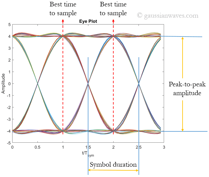
The eye diagram can show the transmission quality of digital signals. Approximation of signal to noise clock timing jitter and skew. In telecommunication an eye pattern also known as an eye diagram is an oscilloscope display in which a digital signal from a receiver is repetitively sampled and applied to the vertical input while the data rate is used to trigger the horizontal sweep. A good way to discriminate between jitter and noise is to create an eye diagram.