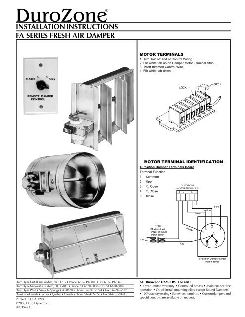
Durozone Wiring Diagram. We confirmed today thanks to a helpful customer how another durozone damper wires using 3 wires even though it has 5 terminals. Converting a 2 wire zone control board to operate a belimo lmb 3wire damper.

Following are simple step by step installation instructions and wiring diagrams for the smz ac system. Equipment the upper left terminal strip is for wiring the equipment to the smz panel. If your motors looks different than this see our other posts about damper wiring.
Equipment the upper left terminal strip is for wiring the equipment to the smz panel.
Using the connectors on the harness wire safety switch in series with the limit circuit as indicated in the appliance wiring diagrams and figure 2. Back to durozone menu durozone the links below are in pdf format. When all zones are satisfied the position of the damper is controlled by the openclosed switches on the panel. Bh kit1 honewell to belimo lmb24 lmb24 kit2 ztech beutler retrofit kit.