Directed Electronics Inc 528t 12v Accessory Pulse Timer Wiring Diagrams. Read honest and unbiased product reviews from our users. Pulse timer with adjustable delay triggered by or pulse or state change adjustable timer.

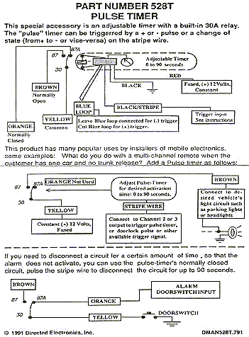
Read or download the diagram pictures electronics inc 528t 12v accessory pulse timer for free wiring diagrams at burrowdemoagriyacom. Red fused 12vdc constant black chassis ground black stripe input pulse from alarm brown87 timed output to device yellow30 chassis ground. Read or download the diagram pictures electronics inc 528t 12v accessory pulse timer for free wiring diagrams at color wire diagraminternapolicalcioit.
Pulse timer with adjustable delay triggered by or pulse or state change adjustable timer.
Dei 528t pulse timer wiring is this the correct way to wire up a 528t to get a timed output pulse from a 5 second alarm input pulse. Select your cookie preferences. Pulse timer with adjustable delay triggered by or pulse or state change adjustable timer. 0 60 seconds.