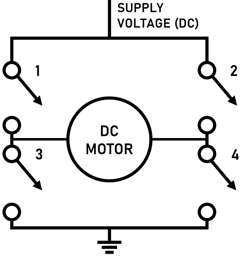
Dc Motor Circuit Diagram Pdf. Two pairs of darlington transistors q1q4 and q2q3 are set up as an h bridge. The negatives of all the hall sensors may be assumed to be grounded.

As said earlier our clock is a 12 hour clock. Two pairs of darlington transistors q1q4 and q2q3 are set up as an h bridge. The negatives of all the hall sensors may be assumed to be grounded.
Most bldc motors have a three phase.
Receiving from point a to aim b. Two loop multiple source. So counts from 0 to 9 then s1 becomes 1 s0 counts again. Theres a diode across the emitter and collector of each transistor to prevent back emf from the motor causing damage to the transistors.