Block Diagram Of Zero Crossing Detector. In the modem a digital pll. Frequency discriminator zero crossing detector phase locked loop foster seely discriminator ratio detector fm transmitter block diagram.
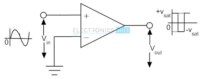
You can use a combination of sign block from simulinkmath operations library and saturation block by adjusting the limits of saturation block to 1 and 0. For example cascading 5 stages provides 10 bit resolution. Here the input signal v i is provided to the inverting terminal of the op amp while the non inverting terminal is grounded by making use of two resistors r 1 and r 2.
Vout 0 if fi fc.
Figure 10 shows a block diagram of the pulse averaging discriminator. As we can see that analog input signal is provided at the inverting terminal of the op amp. 5 shows the basic building block. Working of zero crossing detector circuit.