Bias T Circuit Diagram. The combined port connects to the device which sees both the bias and rf. For vhf use 16 turns of.
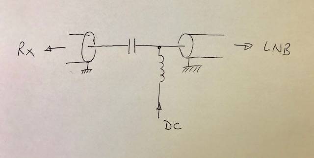
This circuit provides some stabilization for lesser changes. The bias t circuit can either be purchased ready made or manufactured according to the following design right. What about the rf power.
Typical circuit diagram of poc systems 3.
4 is a schematic drawing of a zero loss bias t according to an embodiment of the present invention. 50 ohm and 75 ohm models. The simplest bias tee would have a. A bias tee is a three port network used for setting the dc bias point of some electronic components without disturbing other components.