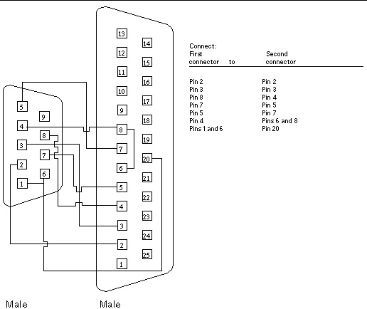
25 Pin Wire Diagram. The dbf has a female 25 pin line printer port input to be used with a maletypical wiring schematic a typical wiring schematic diagram is provided in figure although it is designed for uimxx stepper motor driver it may be used for other stepper motor drivers. Db25 wiring diagram aviom analog input and output modules with db25 multi pin connectors are wired to jacks found on aviom products are numbered according to the diagram.

Then the rs232 wiring was condensed into the 9 pin connector a victim of evolution if you like. This is achieved by increasing the wire twists better shielding drain wire and increased wire diameter. Rs232 port db 25 pin.
51 25 pin d sub connector to tcu adapter cable figure 1 looking into 25 pin d sub connector figure 2 connector this is a male connector number x18500 comprised of 25 female pins and mates with a female connector with 25 male pins on the tcu adapter cable.
Connector usually contains two or more parallel rows of pins or sockets surrounded by a d shaped metal shield that provides mechanical support ensures correct orientation and screen against electromagnetic. 9 rows 9 pin to 25 pin serial. It shows the components of the circuit as simplified shapes and also the power as well as signal connections in between the devices. The following diagrams depict the cable wiring between a dnc workstations communications ports either the standard built in com1 and com 2 or rocketport expansion ports and most cncs.