2 1 Mux Logic Diagram. 16 to 1 multiplexer truth table. Verilog code for 21 mux using gate level modeling.
So in order to get the final output we need a 2 1 multiplexer. Multiplexer2x1 mux 4x1 muxlogic diagram of 4 x 1 muxlogic diagram of 2 x 1 muxwhat is multiplexerlink for implementation of boolean function using muxhttps. A 2 input mux can implement any 2 input function a 4 input mux can implement any 3 input an 8 input mux can implement any 4 input function and so on.
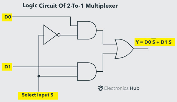
2 input multiplexer design the input a of this simple 2 1 line multiplexer circuit constructed from standard nand gates acts to control which input i.
The figure below shows the block diagram of a 2 to 1 multiplexer which connects two 1 bit inputs to a common destination. 6 to 1 multiplexer. 2 input gates using 21 mux. For simplicity we can write above table as.