1980 Mgb Wiring Diagram. Red wires go to rear side of fuse box. The 45dm4 cei system uses more sophisticated electronics in an external module to give variable dwell and did not use the usual rubber bumper ballasted wiring arrangement.
1971 mgb wiring diagram the schematics show that from 1968 to 1971 a 3 wire hazard flasher unit was used with the third wire feeding the tell tale and this type of. The blue lead u as you observe correctly connects to lug 1 and goes to the dipswitch. 1980 corvette wiring diagram wiring diagram is a simplified gratifying pictorial representation of an electrical circuit.
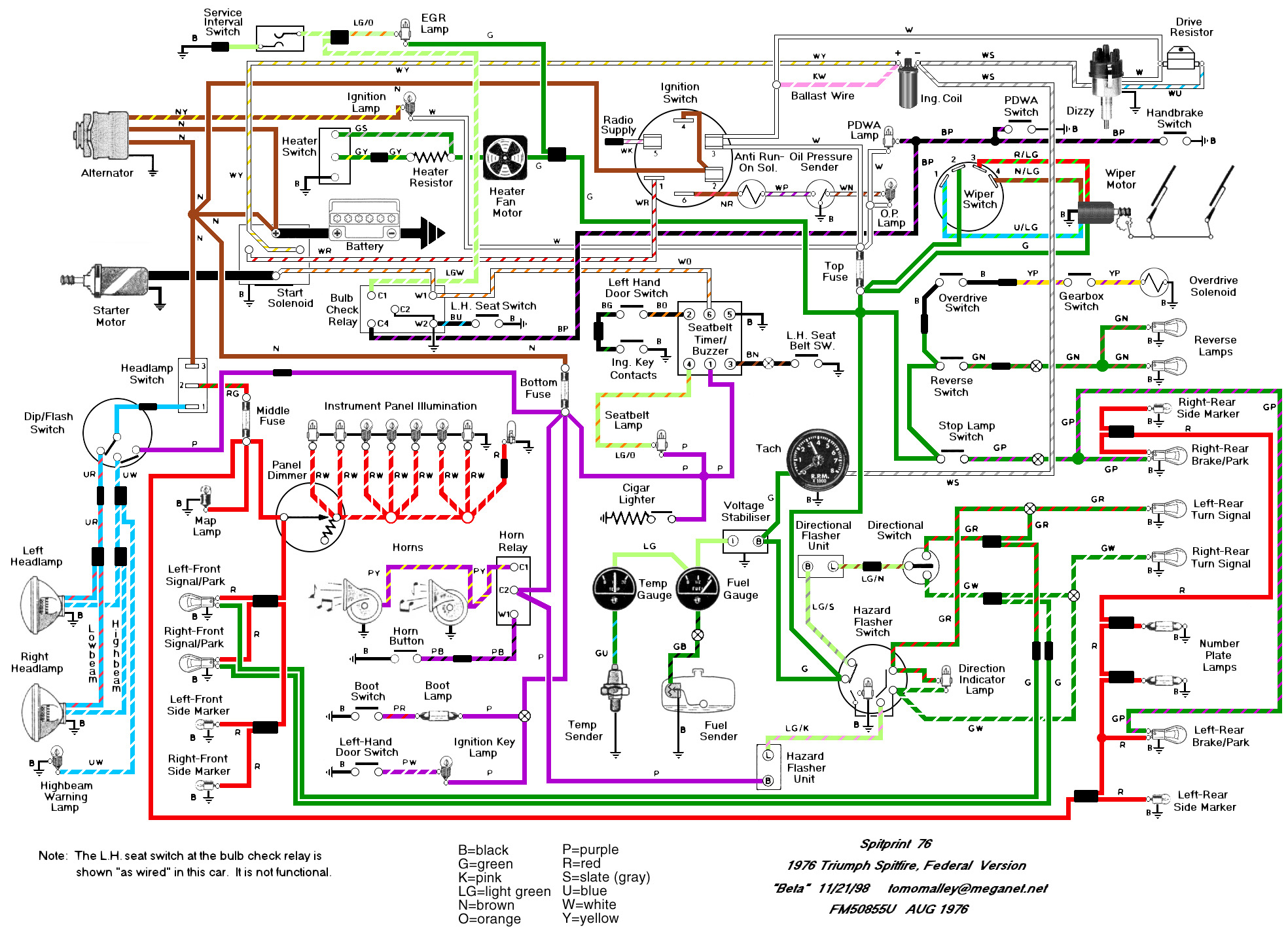
The blue lead u as you observe correctly connects to lug 1 and goes to the dipswitch.
A closer look at the mgbs wiring diagram revealed that no relay was provided which means that the somewhat heavy current feeding the horn was supposed to pass through the horn push. White wires are on the front side. There are only two wires feeding the electronic amplifier on the 80 and they are a white and a whiteblack wire. Has been superseded by loom mgb 7476 360301410000 plplastic.